What additional information do I need to install my equipment that is not in HWU
Applies to
NetApp on-premises products and solutions
Answer
This KB article provides information you need when preparing your site for installation, that may not be available in the Hardware Universe (HWU) portal.
Site information and necessary installation tools
- Environment requirements for your equipment
-
When selecting a location to set up your system, ensure that it meets the following general environmental characteristics:
- Site is free of dust and dirt and other particulate contamination.
- There is sufficient room around your system for access to components and for proper airflow around the system.
- Site meets temperature and humidity requirements for the system.
- Site meets the electrical requirements for your equipment.
- Any changes in the site environment that are caused by unforeseen circumstances due to disaster occurrence or prevention would create an environment that is not suitable for system operation and would impact warranty obligations. These conditions could include, but are not limited to water damage, air quality, fire, fire suppressants or other extinguishing systems.
- Ambient temperature and fan speed considerations
-
- NetApp systems have variable speed cooling fans. At higher ambient temperatures, fans will spin faster and consume more power. This may counteract some energy savings anticipated by raising the ambient temperature.
- You should operate your system within the NetApp-defined operating temperature range, as defined in the HWU. As the temperature increases, the reliability and life expectancy of electronics and hard disk drives decreases.
- Required tools and equipment
-
Prior to receiving your hardware, ensure that you have the appropriate tools and equipment assembled and ready to use:
- Pallet jack, forklift, hand truck or other mechanized lift, depending on what you receive
- #1 and #2 Phillips head screwdrivers and a flathead screwdriver for cable adapters
- A host or client that can attach to a serial console port
- Null modem cable (optional)
If a mechanized lift is not available, multiple people may be required to install certain NetApp products.
Consult the installation documentation or HWU for specific weight and lifting considerations.
Console pinout requirements
- Console port adapter pinout
-
The following table lists the pinout configuration for the RJ-45 to DB-9 dongle shipped with some systems:
RJ-45
Signal
DB-9 (Male connector)
1 [not connected]
2 [not connected]
3 (connected to pin 3 on DB-9)
TXD
3 (connected to pin 3 on RJ-45)
4 (connected to pin 5 on DB-9)
GND
5 (connected to pin 4 on RJ-45)
5 [not connected]
6 (connected to pin 2 on DB-9)
RXD
2 (connected to pin 6 on RJ-45)
7 [not connected]
[not connected] 1
8 [not connected] [not connected]
[not connected] 6 through 9
- ASCII terminal console wiring
-
The following table lists the RJ-45 connection pinout for ASCII terminal console wiring:
Pin number
Signal
1
Connected to pin 8
2
Not connected
3
TXD (from system)
4
GND
5
GND
6
RXD (to system)
7
Not connected
8
Connected to Pin 1
DC power connections
If you ordered a DC power version of your product, you may require the following items to fabricate the three-way cables required for DC power connections.
For details about your DC power supply, see the DC power supply documentation that came with your DC power supply. You can also find this documentation on the NetApp Support site.
Attention: Do not mix different AC with DC power supplies in your controller.
- Additional required tools
-
- Wire-stripper
- Soldering tool and pliers
- 12 AWG to 6 AWG x 3 copper wire (length determined by environment)
- 3/16'' flathead screwdriver
System connectivity information
Your system requires the following types of connections:
- Fibre Channel—Connects your controller to disk shelves, Fibre Channel switches, ATTO FibreBridges, tape backup devices, and to other storage devices. They can connect through the following media:
- Copper
- Optical fiber
- SAS—Connects your appliance to SAS disk shelves and other SAS-based equipment. They can connect through the following media:
- Copper cable with Mini-SAS HD connectors
- Copper cable with QSFP connectors
- Optical fiber SAS cable
- Ethernet—Connects your controller to an Ethernet network through the following media:
- Copper
- Optical fiber
Additional cable information is available in HWU and NetApp Support site.
- Fibre Channel connectivity
-
Your controller connects to disk shelves, Fibre Channel switches, ATTO FibreBridges, tape backup devices, and other storage through onboard ports or adapter ports. See HWU for an example of typical connectors used to connect Fibre Channel devices.
The following table lists maximum distances supported by 50 micron multimode fiber optic cables, with LC or SC connectors, connected to dual-port or quad-port Fibre Channel Host Bust Adapters (HBA), Unified Target Adapters (UTA) or ATTO FibreBridges:
Wavelength
(nm)Core size
(microns)Modal Bandwidth
(MHz/km)Distance
(Meters)Card
(speed)850
50
500 (OM2)
500
1 Gb/s
300
2 Gb/s
150
4 Gb/s
50
8 Gb/s
35 16 Gb/s
2000 (OM3)
860
1 Gb/s
500
2 Gb/s
380
4 Gb/s
150
8 Gb/s 100
16 Gb/s
70 32 Gb/s 4700 (OM4) 400 4 Gb/s 190 8 Gb/s 125 16 Gb/s 100 32 Gb/s
- SAS connectivity
- Your controller connects to SAS disk shelves and other SAS-based devices through SAS host bus adapters (HBAs) or onboard ports. See HWU for specific examples of SAS HBAs.
- Ethernet connectivity
- Your controller connects to an Ethernet network through either Ethernet/UTA onboard ports, Ethernet network interface cards (NICs) or Unified Target Adapters (UTA) that support either copper or fiber cabling.
Copper GbE cabling and NICs:
The cabling and network requirements for GbE and 10GbE networks using unshielded twisted pair (UTP) copper cabling are:- Types: Single-port, dual-port, quad-port Connector type -- RJ-45 for all
- Cable type: Category 5, 5E, 6 or 6a unshielded four-pair cable for 10/100-T/100BASE-T/1000BASE-T/10GBASE-T
- Maximum distance: 100m
Optical fiber Ethernet cabling and NICs:- The following cabling and network requirements are for standards-based 10GbE/25GbE/40GbE/100GbE networks that use optical fiber cables
- References: 10 Gigabit Ethernet, 25 Gigabit Ethernet, 40/100 Gigabit Ethernet
The following table lists maximum distances supported by 50 micron multimode fiber optical cables with LC or MPO connectors for Ethernet ports:Wavelength
(nm)
MMFCore size
(microns)Modal
Bandwidth
(MHz/km)Distance
(Meters)Speed
Interface
Type850
50
2,000 (OM3)
300
10 GbE 10GBASE-SR 70 25 GbE 25GBASE-SR 100 40 GbE 40GBASE-SR4 70 100 GbE 100GBASE-SR4 4,700 (OM4)
400
10 GbE 10GBASE-SR 100 25 GbE 25GBASE-SR 125 40 GbE 40GBASE-SR4 100 100 GbE 100GBASE-SR4
- Back-end (cluster, storage, MetroCluster IP) network connections
- Use NetApp-qualified and sold cabling and optics, as documented in the NetApp Hardware Universe HWU.
- Front-end data networking
-
- Using 3rd party optics/cables is permitted, as long as they are similar in technology and compliant with applicable Ethernet standards.
- Generally, you should avoid active copper and active optical technologies, unless NetApp sells and supports a cable using that technology.
- It’s a good idea to use supported cables from the switch vendor, in these scenarios. The customer is responsible for any cable replacements.
Circuit breaker and power outlet balancing
About the requirements:
NEMA: If your equipment is mounted in a rack, the total number of circuit breakers required for your equipment is based on the current draw. You should not load a circuit beyond 80 percent of the rated limit for the circuit.
Example: If you have a 20A circuit, you should load it to no more than 16A of draw.
IEC: If your equipment is mounted in a rack, the total number of circuit breakers required for your equipment is based on the current draw.
Example: If you have a 16A circuit, you should load it to no more than 16A of draw.
Attention: Overloading circuit breakers can lead to tripped breakers or power brownouts that can cause system errors.
- Balancing the load across PDUs
-
A best practice is to plan how to distribute the total load across the PDU banks prior to plugging your system components into them. You should make each bank load as equally as possible (applicable to 3-phase PDUs).
Keep the following considerations in mind when planning to balance the load:- Balancing the load depends on the number of components being connected and location of the component power supply units (PSUs), as shown in the following illustrations.
- You should connect the components to different PDUs on opposite sides of the system cabinet, using the illustrations for reference.
- You should plug each component into the PDU outlet directly across from the component, using the illustrations for reference.
- Examples of balancing the load with a single component
-
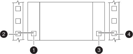
The following illustrations show three examples of connecting the PSUs of a single component, such as a controller in a single chassis, to the system cabinet PDUs.
PSUs on opposite sides of component:
PSUs on same side of component:
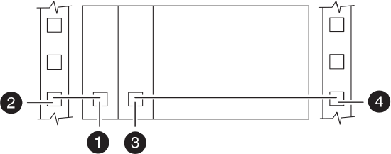
PSUs stacked on same side of component:

1
PSU 1
2
Left PDU outlet
3
PSU 2
4
Right PDU outlet
- Examples of balancing the load with two components
-
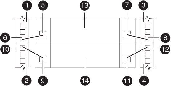
The following illustrations show three examples of connecting the PSUs of two components, such as a component with two controller modules in a single chassis or two components close together, to the system cabinet PDUs.
PSUs on opposite sides of component:
PSUs on same side of component:
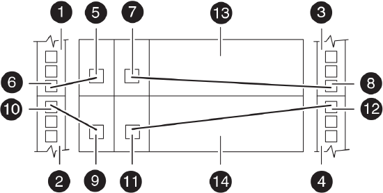
PSUs stacked on same side of component:
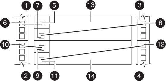
1
Left PDU, bank A
2
Left PDU, bank B
3
Right PDU, bank A
4
Right PDU, bank B
5
PSU 1, component 1
6
Left PDU, bank A outlet
7
PSU 2, component 1
8
Right PDU, bank A outlet
9
PSU 1, component 2
10
Left PDU, bank B outlet
11
PSU 2, component 2
12
Right PDU, bank B outlet
13
Component 1
14
Component 2
Additional Information
additionalInformation_text