How to support Shared Initiator and Shared Target configuration with Array LUNs in a MetroCluster environment
Applies to
- MetroCluster
- ONTAP 9
- FlexArray
Answer
This document outlines the shared initiator and shared target configuration support with Array LUNs in a MetroCluster environment.
Sharing of Initiator and sharing of target in a MetroCluster Configuration with Array LUNs is supported starting with Data ONTAP 8.3
Note: A minimum of four target ports are required for a MetroCluster with array LUNs.
Being able to share a given FC initiator port or target ports is useful for organizations that want to minimize the number of initiator or target ports used.
For example, an organization that expects low I/O usage over an FC initiator port or target ports might prefer to share FC initiator port or target ports instead of dedicating each FC initiator port to a single target port.
However, sharing of initiator or target ports can adversely affect performance.
Supported configuration:
Supported MetroCluster for Shared Target with array LUNs:
- 4/8-node MetroCluster configuration, where initiators are sharing target ports from the same site
- 4/8-node MetroCluster configuration, where initiators are sharing target ports from both the local and remote site
Supported MetroCluster for Shared Initiator with array LUNs:
- 2-node MetroCluster configuration, where initiators are shared across array target ports from the same site
- 4/8-node MetroCluster configuration, where initiators are shared across array target ports from the same site
- 2-node MetroCluster configuration, where initiators are shared across array target ports from both the local and remote site
- 4/8-node MetroCluster configuration, where initiators are shared across array target ports from both the local and remote site
Additional Information
Planning a MetroCluster with array LUNs for Shared Target Ports:
Connecting a maximum of two Data ONTAP FC initiator ports to a single target port on the storage array is supported. Each target port is zoned into two FC initiator ports.
The rules for this configuration are as follows:
- Each node can share, at the most, one FC initiator port with the same target port.
- All storage arrays must be from the same vendor and model family.
- The best practice for zoning is to have each FC initiator-target port pair in a separate zone (1:1).
Example configuration: Shared target ports:
4/8-node MetroCluster where initiators are sharing target ports from the same site.
The below diagram shows a 4-node MetroCluster configuration, where initiators are sharing target ports from the same site with the respective zoning information
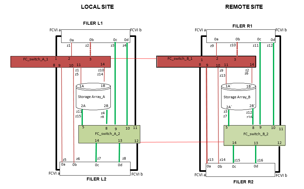
For 8-Node MetroCluster, to configure the switch zoning, you can use the zoning examples of the above 4-node MetroCluster for the first DR group. To configure zoning for the second DR group, follow the same example and requirements for the FC initiator ports and array LUNs belonging to the controllers in the second DR group.
4/8-node MetroCluster where initiators are sharing target ports from both local and remote site.
The below diagram shows a 4-node MetroCluster configuration where initiators are sharing target ports from both local and remote site with the respective zoning information
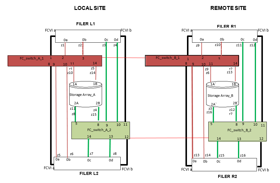
For 8-Node MetroCluster, to configure the switch zoning, you can use the zoning examples of the above 4-node MetroCluster for the first DR group. To configure zoning for the second DR group, follow the same example and requirements for the FC initiator ports and array LUNs belonging to the controllers in the second DR group.
Planning a MetroCluster with array LUNs for Shared Initiator:
Connecting an FC initiator port on a Data ONTAP system to up to four target ports on storage arrays is supported.
The rules for this configuration are as follows:
- All storage arrays must be in the same vendor model family.
Storage arrays in the same family share the same performance and failover characteristics.
For example, storage arrays with different architectures would be in different families even though other characteristics might be the same. See the FlexArray Virtualization Implementation Guide for Third-Party Storage for details about the models in the storage array families for your vendor. - A single FC initiator port can connect to up to four target ports on multiple storage arrays.
- The best practice zoning recommendation is to put each FC initiator-target port pair in a separate zone (1:1), even if the same FC initiator is talking to multiple target ports
Example configuration: Shared FC initiator ports
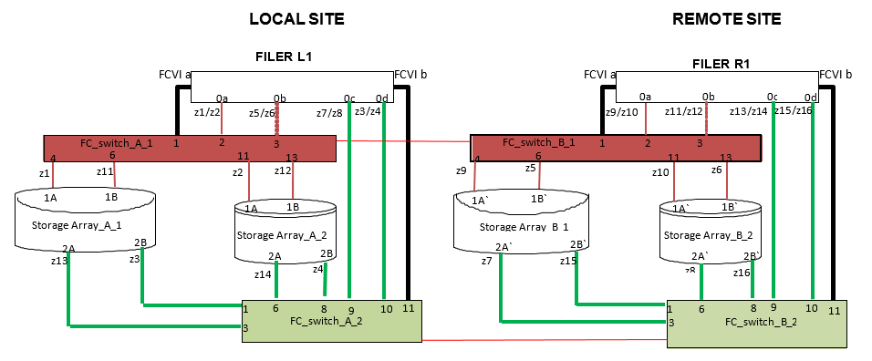
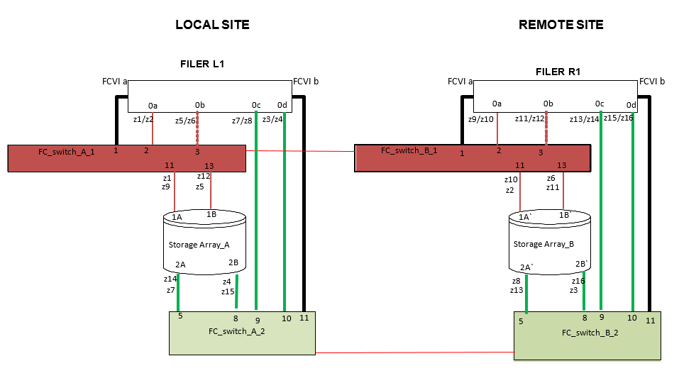
2-node MetroCluster where initiators are shared across array target ports from the same site
The below diagram shows a 2-node MetroCluster configuration where initiators are shared across target ports of the arrays in the same site with the respective zoning information.
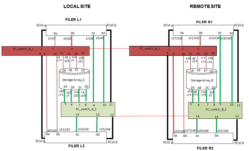
4/8-node MetroCluster where initiators are shared across array target ports from the same site
The below diagram shows a 4-node MetroCluster configuration where initiators are shared across array target ports from the same site with the respective zoning information.
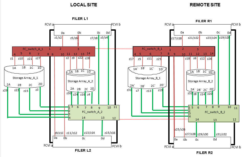
For 8-Node MetroCluster, to configure the switch zoning, you can use the zoning examples of the above 4-node MetroCluster for the first DR group. To configure zoning for the second DR group, follow the same example and requirements for the FC initiator ports and array LUNs belonging to the controllers in the second DR group.
2-node MetroCluster where initiators are shared across array target ports from both local and remote site
The below diagram shows a 2-node MetroCluster configuration where initiators are shared across array target ports from both local and remote sites with the respective zoning information.
4/8-node MetroCluster where initiators are shared across array target ports from both local and remote site
The below diagram shows a 4-node MetroCluster configuration where initiators are shared across array target ports from both local and remote sites with the respective zoning information.
For 8-Node MetroCluster, to configure the switch zoning, you can use the zoning examples of the above 4-node MetroCluster for the first DR group. To configure zoning for the second DR group, follow the same example and requirements for the FC initiator ports and array LUNs belonging to the controllers in the second DR group.